
Using open-circuited or short-circuited transmission line(stub) is a popular matching technique. Such a matching technique is easy to fabricated as stubs can be part of transmission lines(microstrip line or stripe line). Besides, lumped components are avoided.
How stubs work
How do stubs work? Using a smith chart, it’s easy to explain.
Before solving a example, it is quite important to know what a shunt stub bring wo the load. As load can be written as 

Example 1
For a load impedance,design a single-stub (short or open circuit) shunt tuning network to math this load to a
transmission line. Assuming that the load is matched at 1GHz.
Here is the solution. First, we plot the normalized load 
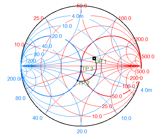
If we insert a longer series line, there is another intersection point on the upper part of the circle 

Double-stub tuning network
Okay, now we know how to match with one shunt stub and one series line, then it will be simple to understand how to match with two shunt stubs and one series line with given electrical length. Let’s look at the example 2 below.
Example 2
For a load impedance
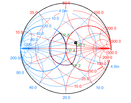
For double-stub matching network, we should insert a shunt stub first, then the series line of given length, a shunt stub at last. Instead of thinking forwards, we’d better solve the problem backwards. From the solution of example 1, we know that if a load can be matched with just one shunt stub, the conductance of the load must be 0.02mS. In smith chart, all the points meeting this requirement are a circle. Then there comes the λ/4 series line. It is necessary that after inserting this series line, the point fall on that unity-normalized-conductance circle. For inserting a series line, the point will rotate clockwise 2βl around the center. So in this example, after inserting the first shunt stub, the point should fall on the unity-normalized-resistance circle, which is circle that unity-normalized-conductance circle rotates counter-clockwise 180 degrees.
Then, we can match the load without tuning the electrical length of two shunt stubs.
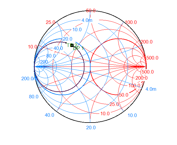
However, if we want to match a load impedance 
Thanks
This is my first blog, thanks for your reading.

Leave a comment